
How We Helped a Biogas Plant Complete Its Digestate Treatment Project
Global biogas policy has evolved from a purely waste treatment orientation to a core component of energy strategy and climate action. The EU, through the Renewable Gas Directive and REPowerEU Plan, has set mandatory targets for biomethane production growth and uses the Carbon Border Adjustment Mechanism to incentivize member states to improve organic waste treatment rates, incorporating biogas into the green hydrogen certification system. The US, under relevant energy legislation, provides multiple incentives such as production tax credits and investment tax credits for biogas and biomethane projects, and includes biogas in the Renewable Fuel Standard system. China has incorporated biogas into its rural revitalization strategy and the "Rural Energy Revolution" priority development catalog, updated national standards for automotive biomethane, and promotes the integration of biomethane into urban gas pipeline networks. The global policy framework is shifting from fiscal subsidy-driven to carbon market-driven and quota-mandatory approaches, with more countries incorporating biogas into their Nationally Determined Contributions.
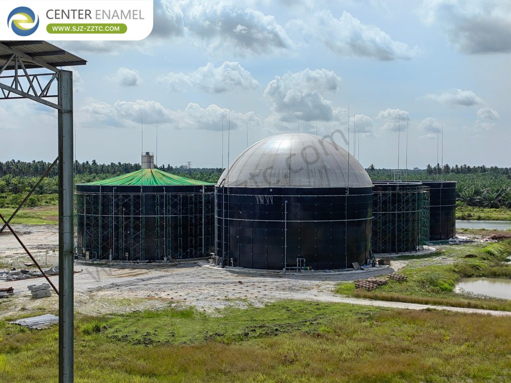
This policy momentum translates into concrete engineering demands: projects must now meet stricter discharge standards, recover more energy, and operate reliably for decades. Meeting these demands requires both durable tank infrastructure-where GFS Tanks have become the mainstream choice-and optimized biological processes such as the USR Process for high-solids feedstocks.
Why GFS Tanks Outperform Traditional Concrete in Corrosion Resistance
Center Enamel's independently developed double-sided double-layer enameling technology is the industry's leading coating anti-corrosion technology, with corrosion resistance completely surpassing concrete tanks. Concrete tank interiors are riddled with pores, allowing wastewater and acid/alkaline media to easily penetrate and corrode the structural layer. Long-term use leads to irreversible problems such as internal wall spalling, water seepage, and rebar corrosion, which are difficult to repair and cannot be fundamentally resolved.
GFS Tanks feature high-temperature enameling on both the interior and exterior surfaces of steel panels, with a dense, non-porous enamel finish that completely blocks corrosive liquids and biogas permeation. The enamel layer has extremely strong chemical stability, resisting acids, alkalis, salts, and microbial corrosion. Concrete tanks will develop extensive corrosion and leakage after 5–8 years of use, while GFS tank anti-corrosion service life can exceed 30 years, with no need for frequent internal lining repairs throughout the service life, significantly reducing long-term anti-corrosion maintenance investment and fundamentally eliminating environmental risks of medium leakage contaminating sites and groundwater. Compared to traditional concrete and FRP tanks, GFS tank coatings have no risk of peeling or blistering, and are adaptable to highly corrosive conditions such as palm oil mill effluent, livestock manure, and chemical high-salinity wastewater, with outstanding long-term comprehensive cost advantages.
| Comparison Factor | Traditional Concrete Tanks | Center Enamel GFS Tanks |
| Anti-corrosion service life | 5–8 years before major degradation | Exceeding 30 years |
| Surface structure | Highly porous; prone to penetration | Dense, non-porous enamel finish |
| Maintenance requirement | Frequent lining repairs | No internal lining repairs needed |
| Chemical resistance | Limited; degrades with acids/alkalis | Resists acids, alkalis, salts, microbial corrosion |
| Leakage risk | High after 5–8 years | Negligible |
| Adaptability | Poor for high-salinity/high-corrosion media | Excellent for POME, manure, chemical wastewater |
USR Process: How the Reaction Sequence Handles High-Solids Wastewater
High-solids organic wastewater, after simple pretreatment to remove large debris, is uniformly fed into the reactor through the bottom distribution system. The upward flow drives solid substrates and anaerobic sludge to slowly rise and thoroughly mix. In the sealed anaerobic environment, microorganisms sequentially hydrolyze/acidify and then methanogenically ferment, degrading macromolecular organic pollutants and generating biogas and treated water. Without complex separation structures, gentle hydraulic disturbance prevents clogging. The mixed liquor rises to the upper portion of the reactor where natural gas-liquid-solid separation occurs. Biogas is collected, effluent overflows, and solid sludge and unreacted substrate settle back to the lower reaction zone for continued reaction, with a small amount of aged sludge periodically discharged-continuous stable operation. This simplified internal structure is what allows the USR Process to tolerate suspended solids levels that would clog conventional reactors.
Standardized Digestate Treatment Solutions for Biogas Plants
Treatment focuses on nitrogen and phosphorus removal, desalination, and polishing-suitable for the unique water quality of low organics and high nutrients. The mainstream approach is a "pretreatment + biological nitrogen removal + advanced polishing" system. Pretreatment is minimal, requiring only simple filtration to remove trace suspended solids-no complex solid-liquid separation or organic degradation steps are needed. The main stage uses AO or A²O multistage biological nitrogen removal processes to target high ammonia nitrogen, total nitrogen, and total phosphorus-addressing the core eutrophication issue. For high-salinity digestate, coagulation/sedimentation and membrane treatment for desalination ensure effluent compliance. The entire process requires no high-intensity organic degradation units, with simplified flow, stable operation, strong shock load resistance, convenient O&M, and suitability for the stable single-component digestate.
| Treatment Stage | Function | Key Target Parameters |
| Pretreatment | Simple filtration of trace suspended solids | SS removal |
| Biological nitrogen removal (AO / A²O) | Multistage nutrient removal | Ammonia nitrogen, total nitrogen, total phosphorus |
| Desalination (coagulation + membrane) | Salinity reduction for high-salinity digestate | Salinity, effluent compliance |
| Advanced polishing | Final compliance assurance | Residual nutrients, COD |
Center Enamel's Smart Manufacturing Base Scale
Center Enamel's core intelligent manufacturing base is located in Hebei Province, China, covering a total area of over 150,000 m², with a mature Phase I manufacturing facility and a Phase II high-end environmental equipment industrial park-dual-base synergy ensures stable production capacity. The base includes dedicated R&D office buildings, proprietary material laboratories, and finished product testing centers, with full-process quality control systems meeting ISO, NSF, CE, and other international standards. The facility operates to green manufacturing standards, certified as a Provincial Green Factory-balancing efficient production with energy conservation and environmental responsibility.
Center Enamel Design Team: Engineering GFS Tanks and USR Process Integration
The design team includes senior engineers registered in the Hebei Provincial Science and Technology Expert Database, with design standards aligned with strict European/American high-end equipment safety standards. The team can provide complete integrated design for differentiated overseas projects in livestock biogas, POME, municipal wastewater, hazardous waste storage, seawater desalination, and more-covering tank structure, anti-corrosion/sealing systems, biogas piping, and anaerobic process integration.
Pre-design thoroughly investigates local seismic zone, wind pressure, soil bearing capacity, water quality corrosivity, and local environmental discharge standards-applying thickened panels, reinforced anchored bases, and optimized sealing/corrosion structures as needed. Complete customized equipment solutions can be tailored to customer plant area, wastewater load, treatment targets, and budget-balancing safety, economics, and local adaptation-providing compliant, stable, and highly adaptable equipment structural design support for global environmental projects. This integrated design capability is what allows GFS Tanks and the USR Process to function as a single, coordinated system rather than separate components.
Gas Holder: Independent Double-Membrane Biogas Storage
Center Enamel's Gas Holder (independent double-membrane biogas holder) is a ground-mounted biogas storage device installed independently from the fermentation tank. It adopts a double-layer high-strength membrane structure, with the inner membrane forming the gas storage cavity and the outer membrane forming the protective shell. Continuous aeration between the inner and outer membranes maintains constant positive pressure, ensuring stable sealing of the gas storage cavity. The Gas Holder is installed separately from the fermentation tank and connected via biogas transmission pipelines. Biogas produced from the fermentation tank is sent to the holder for storage after desulfurization and dehydration, then pressure-regulated and stably delivered to end-use equipment, enabling separated management of biogas production, storage, and utilization.
The gasholder volume can be customized from tens to thousands of cubic meters to meet storage and peak-shaving requirements for different production rates and consumption cycles. The Gas Holder is equipped with a comprehensive safety control system, including biogas leak detection, inner membrane overpressure protection, emergency flare stack, and lightning protection grounding, ensuring full operational safety. The membrane material uses high-strength PVDF outer membrane and biogas-corrosion-resistant inner membrane, with a service life of over 15 years. Maintenance is simple, requiring only periodic checks of membrane integrity and aeration system operation, with significantly lower lifecycle maintenance costs than steel gasholders.
| Gas Holder Feature | Specification |
| Structure | Independent double-membrane, ground-mounted |
| Inner membrane | Biogas-corrosion-resistant material |
| Outer membrane | High-strength PVDF |
| Pressure control | Continuous aeration between membranes |
| Volume range | Tens to thousands of cubic meters |
| Service life | Over 15 years |
| Safety systems | Leak detection, overpressure protection, emergency flare, lightning grounding |
| Maintenance | Periodic membrane and aeration checks |
Frequently Asked Questions
Why are GFS Tanks preferred over concrete for biogas digestate projects?
GFS Tanks use a dense, non-porous enamel coating that resists acids, alkalis, salts, and microbial corrosion. With a service life exceeding 30 years and no need for internal lining repairs, they eliminate the leakage and spalling problems concrete tanks develop after 5–8 years.
How does the USR Process prevent clogging with high-solids wastewater?
The USR Process eliminates complex three-phase separators and relies on gentle upflow hydraulics to mix solids and sludge. Flocculent sludge operates stably without strict granulation, and natural gas-liquid-solid separation occurs in the upper zone-preventing clogging and sludge washout.
What does digestate treatment typically involve?
Digestate treatment focuses on nitrogen and phosphorus removal, desalination, and polishing using a "pretreatment + biological nitrogen removal + advanced polishing" system. AO or A²O processes handle high ammonia nitrogen, while coagulation and membrane treatment manage high salinity.
Ready to integrate GFS Tanks and the USR Process into your biogas plant? Contact Center Enamel today-our design team will deliver a customized digestate treatment and biogas storage solution tailored to your project.