
Biogas Plant Process Flow: From Feedstock to Energy
A biogas plant operates as a continuous loop: feedstock is received and conditioned, digested in an oxygen-free reactor at 35-38 C to release 55-65% methane biogas, the gas is buffered or upgraded, and then converted to power, heat, or vehicle fuel, with the digestate returned as fertilizer. Understanding each stage is what lets an owner predict output, staffing, and maintenance before commissioning.
1. Feedstock Reception and Conditioning
Waste arrives, is weighed and screened, then mixed and heated to the mesophilic band. Consistent feed protects the biology and keeps the gas rate steady; sudden loads of grit or toxins are the most common cause of upset. Conditioning is where many plants add co-substrates to balance C:N toward the 20-30:1 target.
2. Anaerobic Digestion (Core Stage)
The reactor holds biomass at 35-38 C with no oxygen and converts organics to biogas at 0.30-0.45 m3 per kg COD removed, about 55-65% methane. CSTR suits slurry; UASB/EGSB suits soluble high-strength streams. The tank must resist acidic, H2S-bearing liquor, which is why bolted Glass-Fused-to-Steel (GFS) is widely used.
3. Gas Collection and Buffering
| Stage | What happens | Key parameter |
| Reception | Screen, mix, heat feed | 35-38 C feed |
| Digestion | Bacteria make CH4 + CO2 | 0.30-0.45 m3/kg COD |
| Gas buffer | Decouple supply/demand | Low-pressure holder |
| Conversion | CHP or upgrading | 95-99% CH4 if upgraded |
| Digestate | Stabilize, store, spread | Fertilizer outlet |
4. Energy Conversion
A combined heat and power (CHP) unit returns 35-45% as electricity and 80-90% as total energy; the heat offsets process demand. Where vehicle fuel or grid injection is the goal, an upgrading skid lifts the gas to 95-99% methane. Each downstream package is sized from the actual gas volume.
5. Digestate Handling
The liquid and solid residue is separated, stabilized, and stored for land application. Treating it as a product, not a waste, closes the nutrient loop and protects the plant's permit. GFS storage tanks resist the corrosive liquor and ship flat-pack for fast assembly.
Project Case Study
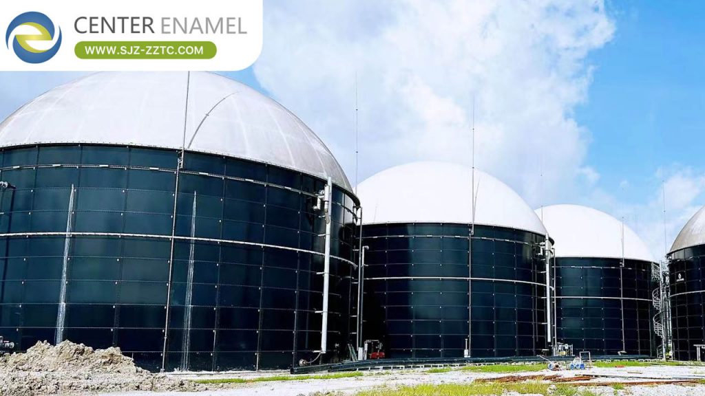
Malaysia Biogas Project. A plant built with 5 GFS tanks totalling 27,000 m3, producing 22,000 m3 of biogas per day at about 80% digestibility — an operating example of the full daily loop from reception through digestion and gas collection at scale.
| Project | Malaysia Biogas Project |
| Location | Malaysia |
| Industry | Renewable Energy / Agro-industry |
| Application | Biogas plant - daily process loop |
| Product | 5 GFS tanks (5,400 m3 each, 24.46 x 12 m) |
| Output | 22,000 m3 biogas/day |
| Status | Delivered 2026 |
About Shijiazhuang Zhengzhong Technology Co., Ltd (Center Enamel)
Shijiazhuang Zhengzhong Technology Co., Ltd (Center Enamel) supplies the manufacturing capability at the core of the process flow: bolted GFS digester and buffer tanks are produced in a controlled factory where glass is fused to steel at 820-930 C, forming an inert, impermeable barrier against corrosive digestate. Tanks are built to ISO 28765 and AWWA D103, shipped flat-pack, and assembled on site — the repeatable hardware the daily loop is built around.
Advantages and Limitations
A well-run loop turns a disposal cost into energy and fertilizer. Limits: feedstock consistency and a skilled operator matter; and the digester is only one package, so integrate it early with gas and energy equipment suppliers.
Comparison: Enclosed Plant vs Open Lagoon
| Factor | Enclosed biogas plant | Open lagoon |
| Energy recovery | High (CHP / CBG) | Low / none |
| Odor control | Enclosed | Poor |
| Land use | Compact tanks | Large footprint |
| Capital | Higher | Lower |
A biogas plant is a continuous loop of reception, digestion, gas buffering, conversion, and digestate handling. Its core is the digester and buffer tankage; size them to feedstock and gas demand. Send your feedstock profile and we will map the process flow and size the GFS tankage for your plant.
Frequently Asked Questions (FAQ)
Q1: What is the daily process flow of a biogas plant?
A: Receive and condition feedstock, digest at 35-38 C, collect 55-65% methane gas, convert to power or fuel, and return digestate as fertilizer.
Q2: How is feedstock conditioned?
A: Screened, mixed, and heated to mesophilic temperature; co-substrates balance C:N toward 20-30:1.
Q3: What tank capacity is available?
A: GFS digester and buffer tanks from 200 m3 to 60,000 m3.
Q4: How much energy does the gas yield?
A: A CHP returns 35-45% as electricity and 80-90% as total energy.
Q5: What standards apply to the tanks?
A: GFS tanks follow ISO 28765 and AWWA D103; the quality system is ISO 9001.
Q6: What feedstock suits a biogas plant?
A: Manure, food waste, sewage sludge, and agro-industrial residues with sufficient organic load.
Suggested CTA
Share your feedstock type and daily volume. We will map the process flow and size the GFS digester and buffer tankage for your plant.