
Center Enamel GFS Tanks, CSTR Process & Full-Chain Biogas Solutions
Global biogas policy has evolved from a purely waste treatment orientation to a core component of energy strategy and climate action. The EU, through the Renewable Gas Directive and REPowerEU Plan, has set mandatory targets for biomethane production growth and uses the Carbon Border Adjustment Mechanism to incentivize member states to improve organic waste treatment rates, incorporating biogas into the green hydrogen certification system.
The US, under relevant energy legislation, provides multiple incentives such as production tax credits and investment tax credits for biogas and biomethane projects, and includes biogas in the Renewable Fuel Standard system. China has incorporated biogas into its rural revitalization strategy and the "Rural Energy Revolution" priority development catalog, updated national standards for automotive biomethane, and promotes the integration of biomethane into urban gas pipeline networks. The global policy framework is shifting from fiscal subsidy-driven to carbon market-driven and quota-mandatory approaches, with more countries incorporating biogas into their Nationally Determined Contributions.
CSTR Reaction Process: Continuous Feed, Mixing & Biogas Generation
CSTR operates in continuous feed, continuous reaction, and intermittent/continuous sludge discharge mode, with a concise and coherent process flow. High-solids organic wastewater, after pretreatment to remove large-particle impurities, is fed at a constant rate into the sealed anaerobic reactor via feed pumps. Continuous mechanical stirring maintains uniform mixing throughout the reactor, creating a stable anaerobic environment. Within the reactor, acidogenic bacteria and methanogens decompose macromolecular organic matter in stages, first hydrolyzing and acidifying polysaccharides, proteins, and lipids into volatile fatty acids, then further degrading them into methane and carbon dioxide biogas. Throughout the reaction, no material stratification occurs, pollutants are continuously degraded, treated supernatant overflows from the upper portion of the reactor, aged sludge is periodically discharged from the bottom, and biogas is uniformly collected for resource utilization, maintaining stable sludge concentration and reaction equilibrium for consistent treatment performance.
Biogas Utilization: CHP, Biomethane, Heating & Carbon Credits
After desulfurization, dehydration, and upgrading, biogas can be utilized in multiple high-efficiency applications, achieving closed-loop value conversion of organic waste to energy and resources.
- Biogas CHP: Biogas is fed into gas engines/turbines for power generation—electricity can be grid-sold or self-consumed, with waste heat recovered for digester heating and plant heating—overall energy efficiency exceeding 80%, the most mainstream biogas utilization method.
- Biogas upgrading to biomethane: After carbon dioxide removal to >95% methane purity, it is equivalent to pipeline natural gas and can be injected into city gas networks or compressed as CNG/LNG for vehicles—significant economic benefits.
- Direct combustion for heating: Biogas can be burned directly for boiler heating, sludge drying, agricultural product drying, greenhouse heating, and other industrial/agricultural heating applications—replacing coal/natural gas and reducing fossil fuel consumption.
- Flare combustion for emergency disposal: When biogas production exceeds utilization capacity, it is flared to reduce direct methane greenhouse gas emissions, meeting environmental compliance requirements. Each cubic meter of biogas has a calorific value of approximately 21-25 MJ, can generate 1.5-2.0 kWh of electricity, or replace 0.7-0.8 cubic meters of natural gas.
Large-scale biogas plants produce thousands to tens of thousands of cubic meters of biogas daily, with annual power generation reaching millions to tens of millions of kWh—carbon reductions can be developed as CCER carbon credits for trading income, delivering triple value in environmental management, clean energy, and carbon assets.
Case Study: Malaysia Palm Oil Biogas with GFS Tanks
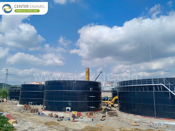
The project uses Center Enamel GFS tanks as the core anaerobic digestion facility with 5 tanks, each with effective volume of 5,400 m³, total effective volume 27,000 m³. Influent COD ≥ 60,000 mg/L, BOD ≤ 25,000 mg/L. After anaerobic digestion, effluent COD drops to below 12,000 mg/L, BOD ≤ 5,000 mg/L—overall organic removal efficiency approximately 80%. Single tank daily biogas production 4,400 m³, total project daily biogas 22,000 m³—stable biogas yield of 0.45 m³ per kg COD removed—efficient biogas energy recovery while solving palm oil processing wastewater pollution.
Center Enamel's Smart Manufacturing Base Scale
Center Enamel's core intelligent manufacturing base is located in Hebei Province, China, covering a total area of over 150,000 m², with Phase I mature manufacturing facility and Phase II high-end environmental equipment industrial park—dual-base synergy ensures stable production capacity. The base includes dedicated R&D office buildings, proprietary material laboratories, and finished product testing centers, with full-process quality control systems meeting ISO, NSF, CE, and other international standards. The facility operates to green manufacturing standards, certified as a Provincial Green Factory—balancing efficient production with energy conservation and emission reduction.
The company has 6 marketing service centers across China, establishing a nationwide production-sales network ensuring stable global order delivery. The base is adjacent to expressway networks and major logistics hubs, with complete container shipping capabilities—supporting simultaneous large-scale tank projects globally. The base employs over 500 staff, with multiple parallel automated production lines—facility scale and production capacity firmly placing it among the global top tier of GFS tank equipment manufacturers.
Full-Industry-Chain Integrated Delivery Capability
Center Enamel is the only company globally integrating proprietary enamel frit R&D, self-manufactured tanks, and EPC general contracting—full-process self-control from solution design, equipment production, cross-border logistics, overseas construction, to post-construction O&M—significantly reducing client coordination and time costs.
Glass-Fused-to-Steel Roof Cover Solution
Glass-Fused-to-Steel Roof is a specialized tank cover solution designed for high air-tightness applications, primarily suited for CSTR anaerobic fermentation tanks and other biogas reactor tanks, serving as a core supporting component in organic waste anaerobic treatment projects. The roof is manufactured with the same material system as glass-fused-to-steel assembled tanks, with steel substrate and high-temperature fused glass coating integrated into one unit. The roof panel joints are equipped with specialized sealant strips and fasteners, achieving high-level overall air-tightness that completely seals biogas generated from anaerobic reactions inside the tank, preventing methane and odorous gas leakage while enabling biogas recovery and on-site odor control.
The product resists long-term corrosion from fermentation liquid and acid/alkaline biogas slurry, and will not be corroded or delaminate due to microorganisms or sulfides in the anaerobic environment. Its service life is synchronized with the glass-fused-to-steel tank, significantly reducing maintenance frequency. The structure employs steel truss supports for the glass-coated panels, providing stable load-bearing capacity. It can accommodate various process openings for mixers, biogas collection, monitoring, and manways, offering high integration. Modular components enable rapid on-site assembly, suitable for large-volume anaerobic fermentation tanks. It is widely used in livestock manure treatment, food waste anaerobic digestion, straw biogas, and municipal sludge disposal projects, and is the mainstream reliable roof selection for anaerobic fermentation tanks.