
Typical Biogas System Configuration: A Comprehensive Engineering Layout
As municipalities and industrial enterprises accelerate toward circular bio-economies, implementing an efficient waste-to-energy facility requires a well-structured engineering layout. A biogas plant is not a single isolated tank; rather, it is a synchronized network of mechanical, biological, and chemical processing units.
Understanding the typical biogas system configuration is essential for project engineers, environmental consultants, and facility operators aiming to maximize organic waste stabilization, optimize methane yield, and ensure long-term structural reliability.
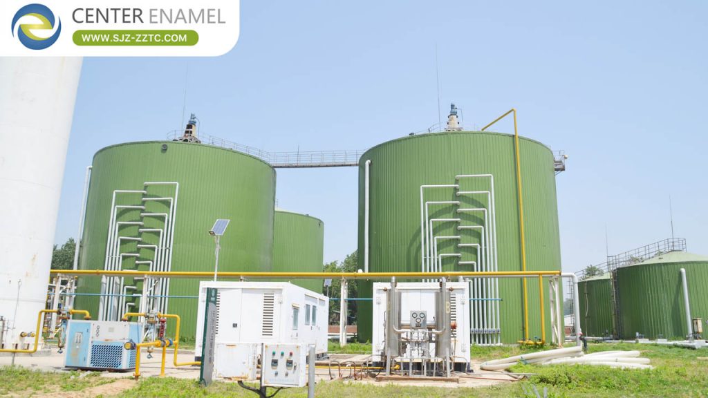
The 5 Core Subsystems of a Typical Biogas Configuration
A standard commercial or industrial biogas plant layout is organized into five primary functional stages:
1. Feedstock Receiving and Pre-Treatment Subsystem
Before organic waste enters the biological reactor, it must be conditioned to prevent equipment clogging and ensure optimal microbial activity.
- Reception & Storage Pits: Secure holding areas for solid or liquid waste (agricultural manure, food scraps, or industrial wastewater).
- Sorting and Screening: Mechanical grates and industrial grinders remove foreign inorganic debris (plastics, metals, grit) and reduce particle size.
- Blending and Homogenization: Mixing tanks combine diverse waste streams with recycled liquid digestate to achieve a uniform solids percentage and stable organic loading rate.
2. The Anaerobic Digestion Subsystem (The Reactor Core)
The heart of the facility where biological conversion takes place in an oxygen-free environment.
- Bioreactor Vessels: Depending on the substrate, facilities utilize Continuous Stirred Tank Reactors (CSTR), Upflow Anaerobic Sludge Blankets (UASB), or Upflow Solids Reactors (USR).
- Structural Containment: Modern installations rely on Glass-Fused-to-Steel (GFS) bolted tanks, which fuse titanium-rich glass to industrial steel to withstand corrosive organic acids and hydrogen sulfide over a 30+ year lifespan.
- Thermal Regulation: Heat exchangers and boilers maintain precise mesophilic (35°C–37°C) or thermophilic (50°C–55°C) operating temperatures.
3. Biogas Collection and Storage Subsystem
As microorganisms break down organic matter, the resulting gas accumulates in the reactor headspace.
- Sealed Piping & Safety Valves: Corrosion-resistant gas lines safely transport raw biogas away from the reactor under monitored pressure, equipped with flame arresters and pressure relief valves.
- Gasholders: Double-membrane fabric domes (often mounted directly on top of GFS digester tanks) expand and contract to buffer fluctuating gas production and consumption rates.
4. Biogas Desulfurization and Upgrading Subsystem
Raw biogas contains moisture and trace impurities that can corrode combustion engines if left untreated.
- Desulfurization: Biological or chemical scrubbers remove corrosive hydrogen sulfide (H2S).
- Moisture Traps: Chillers and condensate traps strip water vapor from the gas stream.
- Upgrading Units: For grid injection or vehicle fuel, systems utilize pressure swing adsorption (PSA), membrane separation, or water washing to remove carbon dioxide (CO2), producing high-purity biomethane (>95% CH4).
5. Digestate Management and Post-Processing Subsystem
The residual material remaining after anaerobic digestion is nutrient-rich digestate.
- Solid-Liquid Separation: Mechanical screw presses or centrifuges separate the digestate into a solid organic fertilizer cake and a liquid fraction.
- Storage and Distribution: Sealed storage tanks hold processed digestate safely prior to agricultural land application.
Comparative Data Table: Typical Biogas Plant Subsystems & Equipment
| Subsystem Stage | Primary Operational Function | Key Engineering Equipment Used |
| 1. Feedstock Pre-Treatment | Sorting, shredding, and homogenizing waste | Industrial grinders, augers, stainless steel mixing tanks |
| 2. Anaerobic Digestion | Enclosed oxygen-free biological reaction | Glass-Fused-to-Steel (GFS) tanks, internal mixers, boilers |
| 3. Biogas Collection | Storing and buffering generated gas safely | Dual-membrane fabric gasholders, PVC/stainless piping |
| 4. Upgrading & Scrubbing | Removing H2S, moisture, and CO2 impurities | Activated carbon filters, membrane separators, chillers |
| 5. Digestate Management | Separating and storing nutrient-rich byproducts | Screw press separators, sealed GFS storage tanks |
Frequently Asked Questions (FAQ)
Q1: What is the most critical component in a typical biogas system configuration?
A: While every subsystem is vital, the anaerobic digester vessel is the core component. It provides the engineered, oxygen-free environment where specialized microorganisms break down organic waste and generate renewable biogas.
Q2: Why are Glass-Fused-to-Steel (GFS) tanks preferred for biogas digesters?
A: GFS tanks combine the structural strength of industrial steel with the chemical inertness of fused glass. They withstand the corrosive organic acids and hydrogen sulfide generated inside anaerobic digesters, offer rapid modular installation, and provide an operating lifespan exceeding 30 years.
Q3: How is temperature regulated within a biogas plant layout?
A: Temperature is regulated using internal heating coils or external heat exchangers connected to boilers or waste-heat recovery systems from combined heat and power (CHP) engines, maintaining steady mesophilic or thermophilic microbial conditions.