
What Are CBG Components?
A CBG (compressed bio gas) system is built from a chain of components: feedstock preparation, an anaerobic digestion reactor, an upgrading skid that removes CO₂/H₂S, a low-pressure buffer holder, a multi-stage compressor with dryer, high-pressure cascade storage, and a dispenser. Each component is engineered to the one before it.
1. Feedstock Preparation and Digester
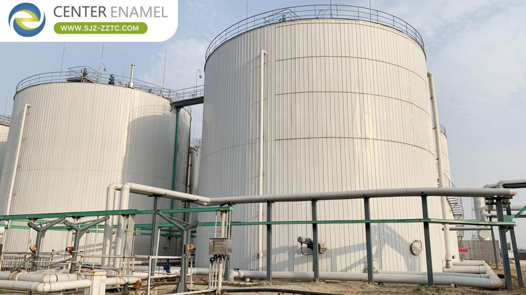
Feedstock is received, homogenized, and fed to an anaerobic digester (typically a wet CSTR at 35–38°C) producing biogas at 55–65% CH₄. The digester tank is the structural core — a bolted GFS tank with an inert, H₂S-resistant glass lining fused at 820–930°C.
2. Upgrading Skid
The upgrading skid raises biogas to 95–99% methane by removing CO₂ (PSA, membrane, or amine) and H₂S/siloxanes. This is where raw biogas becomes vehicle-grade biomethane; the choice of technology sets footprint, power, and impurity limits.
3. Buffer, Compressor, and Dryer
A low-pressure buffer holder (GFS or steel, 4–10 bar) smooths digester variability; a dryer sets the dew point; and a multi-stage reciprocating compressor raises pressure to 200–250 bar. These three interface the clean gas with storage.
| Component | Function | Note |
| Digester (GFS) | Make biogas | 55–65% CH₄ |
| Upgrading skid | CO₂/H₂S removal | to 95–99% CH₄ |
| Buffer holder | Steady feed | 4–10 bar |
| Dryer + compressor | Dew point + pressure | 200–250 bar |
| Cascade + dispenser | Store + fuel | CNG class |
4. Cascade Storage and Dispenser
High-pressure cascade banks store CBG at 200–250 bar; a dispenser transfers it to vehicles or a grid connection, mirroring a CNG station. Instrumentation, relief, and gas detection complete the safety envelope.
Technical Considerations
Component sizing must follow the digestate gas volume, not guesswork: digester HRT 15–30 days, upgrading purity 95–99% CH₄, compression 200–250 bar. Corrosion control (H₂S) protects digester, buffer, and vessels. Pressure vessels follow ASME; GFS holders follow AWWA D103 / ISO 28765.
How to Specify a CBG System
Start from feedstock tonnage and biogas yield, set upgrading purity and daily compression demand, then size each component in sequence. A two-stage CSTR and modular GFS digester shorten the front-end schedule and de-risk deployment.
Project Case Study
Zhenyuan Group Biogas Project in Henan. A vehicle-grade methane plant with 650 T/D feedstock digested in CSTR reactors (3 Ø15.29 × 15 m + 1 Ø5.22 × 6 m) yielding 3,000,000 m³ CH₄/year — illustrating the digester component at the heart of a CBG system.
| Project | Zhenyuan Group Biogas Project in Henan |
| Location | Xinzheng, Henan, China |
| Industry | Renewable Vehicle Fuel |
| Application | CBG system — digester component |
| Product | CSTR digester tanks (GFS) |
| Output | 3,000,000 m³ CH₄/year |
| Status | Delivered 2013 |
About Center Enamel
Center Enamel contributes the product technology at the core of a CBG system: bolted Glass-Fused-to-Steel digester and buffer tanks engineered for wet, corrosive, H₂S-bearing biogas duty. The glass-to-steel enamel is fused at 820–930°C for an inert, impermeable barrier, and tanks are built to ISO 28765 / AWWA D103 with CE-EN 1090 where applicable — the durable front end that the upgrading and compression skids build on.
Advantages and Limitations
A modular component chain lets each stage be sized and sourced independently. Limits: integration and guarantees span multiple suppliers, so specify interfaces (gas quality, pressure, dew point) clearly; and corrosion control upstream protects every downstream component.
Comparison: Upgrading Technologies
| Upgrading tech | Note | Typical use |
| PSA | Adsorption | Common, high purity |
| Membrane | Selective permeation | Compact |
| Amine | Chemical scrub | High CO₂ load |
A CBG system chains feedstock prep, AD digester, upgrading skid, buffer, dryer/compressor, cascade, and dispenser — each sized to digestate gas volume. The GFS digester is the durable core. Send your feedstock data and we will scope the digester and buffer tankage for your CBG component list.
Frequently Asked Questions (FAQ)
Q1: What are the main CBG components?
A: Feedstock prep, AD digester, upgrading skid, low-pressure buffer, dryer, multi-stage compressor, cascade storage, and dispenser.
Q2: What does the upgrading skid do?
A: Removes CO₂ and H₂S to raise biogas to 95–99% methane biomethane.
Q3: What tank capacity is available?
A: Center Enamel supplies GFS digester and buffer tanks from 200 m³ to 60,000 m³.
Q4: What pressure does the compressor reach?
A: 200–250 bar for CNG-class CBG storage and dispensing.
Q5: What standards apply?
A: Pressure vessels follow ASME; GFS holders follow AWWA D103 / ISO 28765; ISO 9001 quality system.
Q6: What project experience exists?
A: Henan vehicle-grade methane plant: 650 T/D → 3,000,000 m³ CH₄/year.
Send your feedstock tonnage and component list. We will scope the GFS digester and buffer tankage and align interfaces with your upgrading and compression skids.