
What Is a Buffer Tank? The Hidden Stabilizer in Biogas Plant Operations
In biogas plant design, attention tends to focus on the digester itself-the large, heated, mixed vessel where microorganisms convert organic matter into methane. But experienced operators know that the digester’s performance depends heavily on what happens before and after it. The buffer tank is the quiet component that makes stable operation possible.
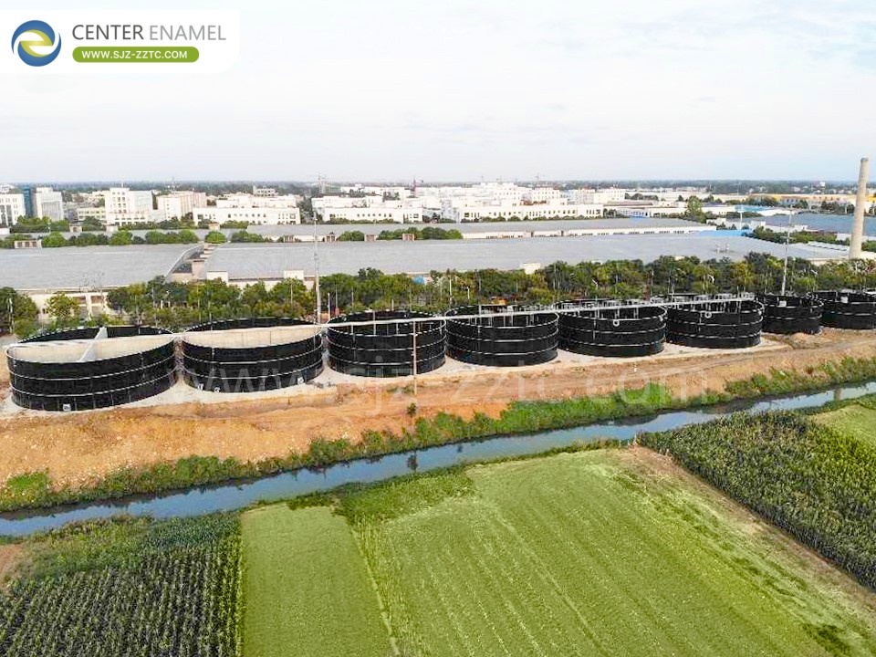
A buffer tank in a biogas plant is an intermediate storage vessel placed between process steps to absorb fluctuations in flow, composition, or temperature. It does not produce biogas directly (in most configurations). It does not perform the main biological conversion. What it does is create time and space-two resources that biological systems desperately need. Without adequate buffering, a digester fed intermittently or with variable substrate will experience shocks that reduce gas yield and can lead to acidification or washout.
This article explains the roles buffer tanks play in biogas plants, the different types used, and the design considerations that determine whether a buffer tank helps or merely occupies space.
The Core Functions of a Buffer Tank in Biogas Plants
A buffer tank serves several distinct purposes depending on where it is placed in the process train. The most common function is flow equalization. Biogas plants often receive substrate intermittently-deliveries arrive during working hours, or hydrolysis reactors operate in batch mode while the main digester requires continuous feed. A buffer tank accumulates material during peak supply and releases it during gaps, allowing downstream processes to operate at a steady rate .
A second function is composition equilibration. When hydrolysis is performed in multiple reactors operating in parallel or in batch sequence, the liquid leaving each reactor can vary in pH, volatile fatty acid (VFA) concentration, and temperature. A buffer tank mixes these streams, producing a more homogeneous feed for the methanogenic reactor. This equilibration reduces the risk of shocking the sensitive methanogens with sudden changes in substrate quality .
A third function, often overlooked, is temperature buffering and heat recovery. In some plant designs, hot digested material passes through a heat exchanger located inside the buffer tank, transferring heat to incoming feed material. This pre-warming reduces the energy required to bring the feed to digester operating temperature, improving overall thermal efficiency .
A fourth function applies to the output side of the digester. A post-digestion buffer tank receives digested slurry before dewatering, providing storage capacity that decouples the continuous digestion process from the batch or daytime operation of dewatering equipment. It may also be aerated to inhibit residual methanogenic activity, preventing unwanted methane emissions downstream .
Feed Buffer Tanks: Smoothing the Input Side
The feed buffer tank sits upstream of the main digester, receiving substrate after pretreatment and before biological conversion. Its sizing depends on the variability of substrate supply and the sensitivity of the downstream process.
In plants processing solid organic waste through a two-phase digestion configuration, hydrolysis reactors operate in batch or semi-batch mode, producing VFA-rich liquid at the end of each cycle. The buffer tank collects this liquid from multiple hydrolysis vessels and equilibrates it before transfer to the biogasification reactor, which operates continuously. Without this buffer, the gasification reactor would receive intermittent pulses of feed, disrupting the steady environment that methanogens require .
For plants receiving liquid substrates such as manure or food-processing wastewater, the feed buffer tank may serve a simpler role: holding incoming material long enough to verify its quality and adjust pH or temperature before it enters the digester. In some designs, the buffer tank is also where dilution water is added to adjust the dry solids concentration to the target range for pumping and digestion.
Hydrolysis Buffer Tanks and Pre-Acidification
In advanced anaerobic digestion configurations, the buffer tank itself may host biological activity. Research on pre-acidification moving bed biofilm reactors (MBBR) has shown that a buffer tank equipped with biofilm carriers can hydrolyze and pre-acidify wastewater or sludge under controlled conditions, reducing the load on the downstream methanogenic reactor and potentially lowering capital costs.
The key design parameters for an MBBR buffer tank are hydraulic retention time (HRT) and hydraulic surface loading (HSL). Operating with an HRT below 12 hours and an HSL in the range of 5 to 70 L/m²/day allows the biofilm to produce organic acids at rates competitive with much larger conventional reactors. The buffer tank in this configuration is not merely passive storage-it is an active pretreatment step that begins the conversion process before the material reaches the main digester .
This approach is particularly relevant for industrial wastewater treatment where space is limited and capital expenditure must be controlled. By integrating hydrolysis into the buffer tank, the overall reactor volume required for the system can be reduced.
Post-Digestion Buffer Tanks and Downstream Stability
The buffer tank on the output side of the digester performs a different but equally important role. Digested slurry leaving a continuously fed digester cannot always be dewatered at the same rate it is produced. Dewatering equipment typically operates during working hours, while the digester runs around the clock. A post-digestion buffer tank absorbs this mismatch, storing digested material until the dewatering stage is ready to process it .
In some facilities, the post-digestion buffer tank is aerated to suppress further methane production. Even after leaving the digester, digested slurry contains residual organic matter and active methanogens. If stored anaerobically, these organisms can continue producing methane, creating a safety hazard and releasing a potent greenhouse gas. Gentle aeration introduces oxygen that inhibits methanogenesis, ensuring that any gas released from the buffer tank is not flammable and reducing the plant’s environmental footprint .
The buffer tank also serves as a sampling and monitoring point. Operators can check the digested slurry’s solids content, pH, and residual gas potential before it proceeds to dewatering, catching problems before they affect downstream equipment.
Design Considerations: Volume, Mixing, and Material Selection
Sizing a buffer tank requires understanding both the variability of the upstream process and the requirements of the downstream process. A tank that is too small cannot absorb fluctuations; a tank that is too large wastes capital and may allow material to sit long enough to develop odors or undergo unwanted biological changes.
For feed buffer tanks in batch-fed systems, the volume should be sufficient to hold at least one complete batch from the hydrolysis reactor, plus a margin for process upsets. In continuously fed plants, the buffer volume is often expressed as a multiple of the hourly feed rate-typically 4 to 12 hours of storage, depending on how variable the supply is.
Mixing is essential for composition equilibration but must be appropriate to the material. Thick slurries may require mechanical agitation, while liquid streams can be mixed by recirculation or gas mixing. Excessive mixing consumes energy unnecessarily; insufficient mixing allows stratification and short-circuiting.
Material selection depends on the chemical environment. Glass-lined bolted steel panels are used in some municipal biogas facilities for corrosion resistance and ease of installation . Insulated tanks help maintain temperature and reduce heat loss, particularly where the buffer tank serves a thermal buffering role. For tanks handling potentially odorous material, covers and odor control connections should be included in the design.
Common Problems and How to Avoid Them
Buffer tanks are simple in concept but can become sources of operational trouble if not properly managed. The most common issue is accumulation of solids. Settling material reduces effective tank volume over time and can lead to anaerobic conditions in what should be an aerated or mixed vessel. Routine sludge surveys and periodic cleaning are necessary.
A second problem is unintended biological activity. A buffer tank that holds VFA-rich liquid for too long without pH control can begin to acidify, potentially damaging tank materials or creating conditions that shock the downstream digester when the material is finally released. Monitoring pH and VFA concentration in the buffer tank provides early warning.
A third issue is foaming, particularly in post-digestion buffers where residual gas is still being released. Foam can block vents, overflow the tank, and create safety hazards. Antifoam dosing or mechanical foam-breaking may be required, and the root cause-often excess protein or lipid content in the feed-should be investigated.
Finally, heat loss from buffer tanks can be significant if they are uninsulated or if residence times are long. For feed buffers that are supposed to deliver material at a controlled temperature, this heat loss translates directly into increased heating demand in the digester. Insulation and, where appropriate, heat recovery from the post-digestion side can mitigate this.
Conclusion
A buffer tank is not the most visible or technically glamorous component of a biogas plant. But it performs a function that no other vessel can replace: it creates the stability that biological systems require. By equalizing flow, equilibrating composition, recovering heat, and decoupling continuous and batch processes, buffer tanks allow digesters to operate at their design capacity rather than constantly recovering from upsets. Whether the application is a large agricultural biogas plant, a municipal wastewater digestion facility, or an industrial anaerobic treatment system, the buffer tank deserves careful attention during design and consistent monitoring during operation.
Frequently Asked Questions
What is the difference between a buffer tank and a mixing tank in a biogas plant?
A mixing tank is designed primarily to homogenize materials, often using mechanical agitators or gas mixing to blend substrates or slurries. A buffer tank is designed primarily to provide storage capacity and time, absorbing fluctuations between process steps. In practice, many buffer tanks include mixing to prevent settling and to equilibrate composition, but the primary design intent-storage and flow equalization-distinguishes them from dedicated mixing vessels.
Where should a buffer tank be located in a biogas plant?
The most common locations are before the main digester (feed buffer), between hydrolysis and methanogenesis (hydrolysis buffer), and after the digester before dewatering (post-digestion buffer). The optimal location depends on where variability enters the process. Plants with intermittent substrate delivery need a feed buffer; plants with batch hydrolysis need an equilibration buffer; plants with daytime-only dewatering need a post-digestion buffer. Many plants use more than one.
Can a buffer tank increase biogas production?
A buffer tank does not produce biogas directly, but it can improve gas yield indirectly by stabilizing the feed to the digester. Methanogens are sensitive to sudden changes in pH, temperature, and substrate concentration. When a buffer tank smooths these fluctuations, the digester operates closer to its optimal conditions, reducing the frequency and severity of process upsets that temporarily suppress gas production. In configurations where the buffer tank hosts pre-acidification biofilm, it may also increase the rate of VFA production, improving the overall conversion efficiency of the system.
Need help sizing a buffer tank or optimizing your biogas plant’s process stability? Contact our engineering team to discuss your project.