
What Is a Sedimentation Tank? A Complete Guide to Gravity Settling in Water and Wastewater Treatment
A sedimentation tank is one of the most fundamental and widely used unit processes in water and wastewater treatment. Its operating principle is elegantly simple: allow water to sit still long enough for suspended particles to settle to the bottom by gravity. Yet this straightforward concept underpins the performance of virtually every municipal treatment plant, industrial pretreatment system, and drinking water facility. This article explains what a sedimentation tank is, how it functions, the main configurations used in practice, and the design and operational factors that determine whether it succeeds or fails.
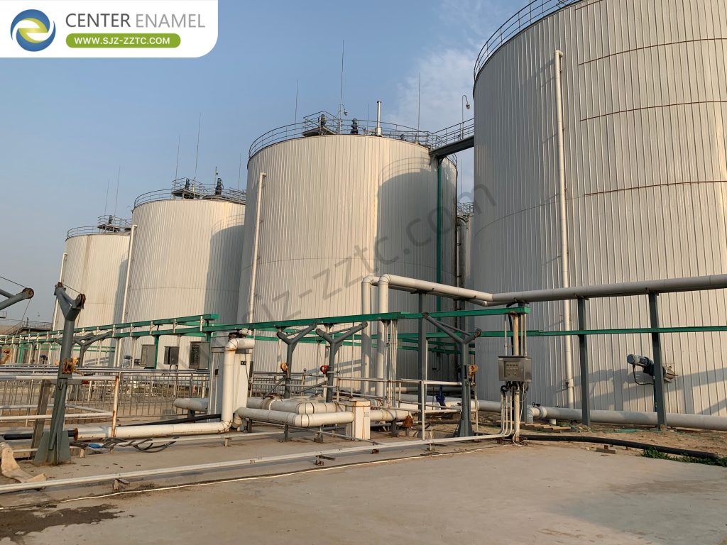
What Is a Sedimentation Tank?
A sedimentation tank, also called a clarifier or settling tank, is a basin designed to remove settleable solids from water or wastewater by gravity separation . The tank provides sufficient hydraulic retention time and quiescent conditions for particles denser than water to sink to the bottom, where they accumulate as sludge, while clarified liquid overflows from the top.
Sedimentation tanks serve two distinct functions depending on their position in the treatment train. Clarification produces a clear overflow, which is the primary goal in most water treatment and secondary wastewater applications. Thickening concentrates the underflow solids, which is important for sludge handling and disposal . Many clarifiers perform both functions simultaneously, though the design emphasis shifts depending on the application.
The physical form of a sedimentation tank varies widely. Circular tanks with rotating scraper mechanisms are common in wastewater treatment, while rectangular tanks with chain-and-flight sludge collectors dominate many water treatment plants . Regardless of shape, every sedimentation tank contains four functional zones: an inlet zone for flow distribution, a settling zone where the majority of particle removal occurs, a sludge zone for solids storage and removal, and an outlet zone for clarified effluent collection .
How Gravity Settling Works in a Sedimentation Tank
The performance of a sedimentation tank is governed by the settling velocity of the particles it must remove. For discrete particles in dilute suspension, settling velocity can be estimated using Stokes' Law, which relates particle diameter, density difference between particle and water, and fluid viscosity. Larger, denser particles settle quickly; smaller, lighter particles settle slowly or not at all.
In practice, settling in treatment tanks rarely follows the ideal discrete-particle model. As particles settle, they may collide and agglomerate, increasing in size and settling faster-a phenomenon called flocculation during settling. In activated sludge clarifiers, the situation is more complex still. All four settling regimes-Type I (discrete), Type II (flocculant), Type III (hindered or zone settling), and Type IV (compression)-occur simultaneously in different regions of the tank . The upper region is dominated by discrete and flocculant settling, while the sludge blanket at the bottom undergoes zone settling and compression.
The key design parameter that emerges from settling theory is the surface overflow rate (SOR), also called surface loading rate. Theoretically, the removal of a particle with a given settling velocity depends on the overflow rate (flow divided by tank surface area), not on the tank depth. This is why shallow, large-area tanks are generally more efficient than deep, small-area tanks for a given flow. In practice, however, some depth is required to prevent disturbance of settled sludge and to accommodate flow distribution and sludge collection equipment .
Primary Sedimentation Tanks: The First Line of Solids Removal
Primary sedimentation tanks are located at the head of a wastewater treatment plant, downstream of screening and grit removal but ahead of biological treatment. Their purpose is to remove settleable suspended solids and a portion of the biochemical oxygen demand (BOD) associated with those solids before the wastewater reaches the biological reactors.
Typical primary clarifiers remove 50–70% of suspended solids and 25–40% of BOD, depending on influent characteristics and tank design . The removal efficiency is strongly influenced by the influent suspended solids concentration and the ratio of settleable to non-settleable solids. Higher influent solids concentrations generally yield higher percentage removals because the clarifier acts as a solids equalization unit .
Primary sedimentation tanks are designed primarily using surface overflow rate and hydraulic detention time. For conventional primary clarifiers, SOR values typically fall in the range of 30–50 m³/m²·day at average flow, with detention times of 1.5–2.5 hours. Chemically enhanced primary treatment (CEPT), which adds coagulants and flocculants ahead of the clarifier, can substantially increase TSS and BOD removal and allow operation at higher overflow rates .
Secondary Clarifiers: Separating Biomass from Treated Effluent
Secondary clarifiers occupy a fundamentally different role in the treatment train. Located downstream of biological treatment-activated sludge, trickling filters, or other biological processes-they separate the biomass generated during treatment from the clarified effluent. In activated sludge systems, the secondary clarifier also performs a critical hydraulic function: it thickens the settled sludge so that a concentrated return activated sludge (RAS) stream can be recycled back to the aeration basin to maintain the mixed liquor suspended solids concentration .
The design of secondary clarifiers is more demanding than primary clarifiers because the solids loading rate, not just the hydraulic overflow rate, governs performance. The sludge blanket must be maintained at a stable depth, and the clarifier must handle fluctuations in mixed liquor suspended solids and flow without allowing solids to escape over the effluent weirs. Typical secondary clarifier SOR values range from 16–32 m³/m²·day at average flow and can be substantially higher at peak flows .
| Parameter | Primary Sedimentation Tank | Secondary Clarifier |
| Location in train | Before biological treatment | After biological treatment |
| Primary design criteria | Surface overflow rate, detention time | Surface and solids loading rates |
| Typical SOR (average flow) | 30–50 m³/m²·day | 16–32 m³/m²·day |
| Key operational concern | Sludge fermentation, scum accumulation | Sludge blanket control, solids carryover |
| Sludge handling | Primary sludge to thickener/digester | RAS recycled; WAS wasted |
Sedimentation Tank Configurations and Design Features
Sedimentation tanks are built in several configurations, each with distinct hydraulic characteristics and applications.
Rectangular tanks are common in water treatment and larger wastewater plants. Wastewater enters at one end and flows horizontally to the outlet at the opposite end. Sludge is collected by a chain-and-flight mechanism that scrapes the floor toward a hopper at the inlet end. Design criteria for rectangular tanks typically specify length-to-width ratios greater than 3:1, longitudinal velocities below 72 m/h, and side wall depths under 5 meters .
Circular tanks dominate wastewater clarifier design. Flow enters through a central feed well and moves radially outward, while clarified effluent overflows a peripheral weir. A rotating scraper mechanism continuously moves sludge to a central hopper for withdrawal. Circular tanks offer good hydraulic stability and are well suited to mechanical sludge collection .
Inclined plate and tube settlers represent an intensification of conventional settling. By placing closely spaced inclined plates or tubes within the tank, the effective settling area is multiplied many times over the footprint area. The shallow depth between plates means particles need travel only a short distance to reach a settling surface. These high-rate clarification systems can operate at two to three times the surface loading rate of conventional tanks and are valuable where space is constrained .
| Tank Configuration | Typical Application | Key Design Feature | Main Advantage |
| Rectangular | Water treatment, large WWTPs | Chain-and-flight sludge collector | Efficient land use in long basins |
| Circular | Primary and secondary wastewater | Rotating scraper, peripheral weir | Hydraulic stability, proven reliability |
| Inclined plate/tube | Space-constrained upgrades | Shallow settling modules | 2–3× higher loading capacity |
| Vertical flow | Package plants, industrial | Upflow through sludge blanket | Compact footprint |
Design Criteria and Performance Factors
Successful sedimentation tank design balances hydraulic loading, solids loading, and physical geometry. The surface overflow rate determines the tank area required for a target particle removal efficiency. The hydraulic retention time ensures adequate opportunity for settling and is typically 3–4 hours for conventional water treatment sedimentation and 1.5–2.5 hours for primary wastewater clarifiers .
Weir loading rate-the flow per unit length of effluent weir-must be controlled to prevent clarified water from drawing floc or sludge particles over the weir. A common design limit is below 300 m³/m·day, with typical design values around 200 m³/m·day . Inlet and outlet baffles are used to distribute flow evenly and prevent short-circuiting, which would reduce effective detention time and allow particles to escape before settling.
Temperature differences between influent and tank contents can create density currents that disrupt settling patterns. Colder influent tends to flow along the bottom of the tank, while warmer influent rises toward the surface. Baffling and proper inlet design help mitigate these effects . Scum accumulation at the surface must be removed regularly, and sludge must be withdrawn before it becomes septic and begins to float or produce odors .
Operational Challenges and Troubleshooting
Sedimentation tanks are mechanically simple but operationally sensitive. Common problems include floating sludge, black or odorous wastewater, scum overflow, poor suspended solids removal, and sludge that is difficult to pump from hoppers .
Floating sludge often indicates sludge fermentation caused by excessive storage time or inadequate withdrawal. Damaged scrapers or plugged sludge pipes can also contribute. The remedy typically involves more frequent sludge removal and inspection of collection equipment. Black wastewater or sludge signals septicity from long residence times or improper sludge removal; flushing pipes and adjusting withdrawal schedules are standard corrective actions. Poor solids removal may result from hydraulic overloading, short-circuiting, or inadequate flow distribution among multiple tanks. Checking flow rates, adjusting pumping schedules, and ensuring uniform distribution are first steps .
Routine maintenance includes inspecting scraper mechanisms, checking weir alignment for uniform overflow, flushing sludge lines, and monitoring sludge blanket depths in secondary clarifiers. The minimum number of tanks at any plant should be two, so that one can be taken out of service for maintenance without interrupting treatment .
FAQ
What is the difference between a sedimentation tank and a clarifier?
The terms are largely interchangeable. “Sedimentation tank” emphasizes the physical process of gravity settling, while “clarifier” emphasizes the function of producing clarified effluent. In practice, both refer to the same type of basin, though “clarifier” is more commonly used in wastewater treatment contexts.
How long does water stay in a sedimentation tank?
Detention time varies by application and design. Conventional water treatment sedimentation tanks typically provide 3–4 hours of retention . Primary wastewater clarifiers usually provide 1.5–2.5 hours. Secondary clarifiers may have shorter hydraulic detention but must maintain sufficient solids inventory for biological process stability.
Can sedimentation tanks remove dissolved pollutants?
No. Sedimentation removes only particles that are denser than water and large enough to settle within the available detention time. Dissolved contaminants require other treatment processes such as biological oxidation, chemical precipitation, adsorption, or membrane separation. Sedimentation is often used as a pretreatment or polishing step in combination with these processes.
Ready to optimize your sedimentation or clarification process? Contact our engineering team to discuss tank design, performance evaluation, and retrofit options for your facility.