
What Is an IC Reactor? Understanding Internal Circulation Anaerobic Technology
In the world of industrial wastewater treatment, few technologies have generated as much interest as the Internal Circulation (IC) reactor. But what exactly is an IC reactor, and why is it becoming the preferred choice for treating high-strength organic wastewater from industries such as breweries, food processing, dairy farms, pulp and paper mills, and slaughterhouses?
The IC reactor represents the third generation of anaerobic treatment technology – a significant advancement over older systems like the Upflow Anaerobic Sludge Blanket (UASB) reactor. Designed to handle high organic loading rates while producing valuable biogas, the IC reactor offers a compact, energy-efficient solution for industries facing stringent environmental regulations and rising energy costs.
This comprehensive guide explains how IC reactors work, their advantages and limitations, and why they are transforming wastewater management worldwide – with insights into how Center Enamel supports these systems with world-class Glass-Fused-to-Steel (GFS) tank solutions.
What Is an IC Reactor? Definition and Overview
An Internal Circulation (IC) reactor is a high-rate anaerobic treatment system designed to degrade organic pollutants in industrial wastewater while simultaneously producing biogas (primarily methane and carbon dioxide). It belongs to the family of expanded sludge bed reactors, characterized by high liquid upflow velocities that keep the anaerobic sludge bed in a fluidized or expanded state .
The IC reactor is often described as "two UASB reactors stacked on top of each other" . This unique design incorporates two gas-separation stages that create an internal circulation flow – hence the name "Internal Circulation" reactor. This internal circulation is powered entirely by biogas generated within the reactor, requiring no external pumping energy.
Key Features at a Glance
| Feature | Description |
| Generation | Third-generation anaerobic reactor |
| Design | Two stacked UASB reactors with internal circulation |
| Height-to-diameter ratio | High (typically 4-8:1) |
| Power source | Self-powered by biogas (no external circulation pumps) |
| Typical COD load | 10,000-30,000 mg/L and higher |
| Biogas methane content | 65-80% |
How Does an IC Reactor Work?
The IC reactor consists of five functional zones that work together to achieve efficient organic degradation and biogas recovery :
Zone 1: Mixing Zone
Wastewater enters the bottom of the reactor and mixes with recirculated effluent and active anaerobic granular sludge. This initial mixing ensures immediate contact between organic pollutants and the biomass responsible for degradation.
Zone 2: First Anaerobic Zone (Lower Chamber)
This is the primary treatment zone, where the majority of organic matter breakdown occurs. The high organic loading rate and dense granular sludge bed create ideal conditions for rapid biogas production. Biogas generated in this zone is captured by the first gas-liquid-solid separator (also known as a three-phase separator).
Zone 3: Second Anaerobic Zone (Upper Chamber)
Wastewater that has been partially treated in the lower chamber flows upward into the second anaerobic zone. Here, remaining organic matter is further degraded. Biogas generated in this zone is captured by a second gas-liquid-solid separator.
Zone 4: Internal Circulation System
This is what makes the IC reactor unique. Biogas captured in the lower chamber rises through a riser pipe, lifting a mixture of water and sludge upward. This creates a natural pumping effect. The gas is then separated at the top, while the water and sludge flow back down through a downer pipe – establishing continuous internal circulation without any mechanical pumps .
Zone 5: Settling Zone
At the top of the reactor, a final settling zone allows any remaining solids to settle back into the reactor. Treated effluent overflows for discharge to subsequent treatment stages (if required) or direct discharge.
IC Reactor vs. UASB: Key Differences
| Parameter | IC Reactor | UASB Reactor |
| Generation | Third-generation | Second-generation |
| Height | Typically 15-25 meters | Typically 5-10 meters |
| COD loading rate | 15-30 kg/m³/day | 5-15 kg/m³/day |
| Hydraulic retention time | 2-8 hours | 8-24 hours |
| Internal circulation | Yes (self-powered) | No |
| Footprint | Very small | Moderate |
| Biogas recovery | Higher (multiple separation stages) | Moderate |
| Suspended solids tolerance | Better due to high upflow velocity | Limited |
| Capital cost | Higher initial investment | Lower initial investment |
| Maintenance complexity | More complex internal structure | Simpler design |
The IC reactor was developed as an improvement upon the widely used UASB (Upflow Anaerobic Sludge Blanket) reactor. Understanding the differences helps explain why IC reactors are increasingly preferred for high-strength applications.
When evaluating IC reactors against UASB systems, the key takeaway is that IC reactors excel in high-strength applications with limited space, while UASB may still be appropriate for lower-strength waste streams or when capital costs are the primary constraint .
Performance Capabilities of IC Reactors
Typical Performance Metrics
IC reactors demonstrate impressive performance across a range of industrial wastewater types:
| Industry | COD Removal | Biogas Yield | Reference |
| Dairy processing | 80-94% | 0.35-0.55 m³/kg COD | |
| Pulp and paper | >80% (at 14 kg/m³/day) | 0.32-0.41 L/g COD | |
| Pharmaceutical lactose | Up to 93.8% | 0.32 L/g COD removed | |
| Vegetable juice waste | 80-94% | 66-69% methane content | |
| Brewery wastewater | 85-95% | 0.35-0.50 m³/kg COD | Industry standard |
Key Performance Advantages
High Organic Loading Capacity
IC reactors can operate at volumetric loading rates of 15-30 kg COD/m³/day – three to five times higher than conventional UASB reactors . This means significantly less reactor volume is required to treat the same amount of organic waste.
Excellent Shock Load Resistance
The internal circulation automatically dilutes incoming wastewater, buffering against sudden changes in concentration or flow rate. This self-regulating mechanism is a major advantage for industries with variable production cycles .
Low Energy Consumption
The internal circulation is driven entirely by biogas. No external pumping energy is required for recirculation, making the IC reactor highly energy-efficient. The only energy inputs are for feed pumping (minimal) and optional heating if mesophilic or thermophilic operation is required.
Compact Footprint
Because IC reactors are tall (15-25 meters) rather than wide, they occupy minimal land area – a critical advantage for facilities with space constraints or expensive real estate.
High-Quality Biogas
The two-stage gas separation produces biogas with methane content of 65-80%, suitable for direct combustion in boilers or Combined Heat and Power (CHP) engines .
Limitations and Challenges of IC Reactors
No technology is perfect, and IC reactors have specific limitations that engineers must consider:
Pre-Treatment Requirements
Suspended solids (SS) must be controlled before entering the IC reactor. High SS levels can accumulate in the reactor, reducing active volume and potentially washing out granular sludge. Most applications require screening or dissolved air flotation (DAF) pre-treatment .
Calcium Management
Industries with calcium-rich wastewater (such as dairy processing) face scaling risks. Calcium precipitation on reactor walls, pipes, and within sludge granules can reduce performance over time. One study of a dairy IC reactor showed that calcium concentrations of 400-600 mg/L led to progressive calcification, requiring periodic maintenance interventions .
Complex Internal Structure
Compared to UASB reactors, IC reactors have more complex internal components – including two three-phase separators, riser pipes, and downer pipes. This complexity can make maintenance and troubleshooting more challenging .
Higher Initial Capital Cost
The taller structure and internal components make IC reactors more expensive to manufacture and install than UASB systems, though the higher loading rates often offset this through reduced footprint and lower civil works costs.
Not Suitable for Low-Strength Wastewater
For wastewater with COD below approximately 1,500-2,000 mg/L, the benefits of internal circulation diminish. UASB or other technologies may be more appropriate for dilute waste streams.
Applications of IC Reactors
IC reactors are particularly well-suited for industries generating high-strength, biodegradable organic wastewater:
| Industry | Typical COD (mg/L) | Why IC Is Suitable | |
| Breweries and distilleries | 3,000-15,000 | High organic load, seasonal variations | |
| Dairy processing | 2,000-10,000 | High fat content, calcium scaling requires careful design | |
| Pulp and paper mills | 1,500-8,000 | High COD, space constraints | |
| Slaughterhouses and meat processing | 2,500-10,500 | High suspended solids, fat, and protein | |
| Food and beverage manufacturing | 2,000-12,000 | Variable composition, shock loads | |
| Palm oil mills | 20,000-60,000 | Extremely high strength, energy recovery potential | |
| Pharmaceutical lactose production | Up to 60,000 | Very high strength, granulation benefits |
Center Enamel: Supporting IC Reactors with GFS Tank Technology
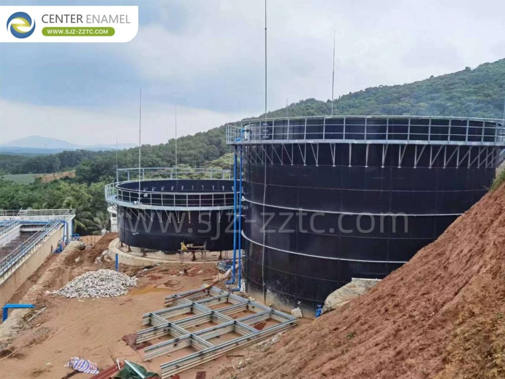
The performance of any anaerobic treatment system depends heavily on the quality of its containment infrastructure. Center Enamel, with over 36 years of experience and a presence in more than 100 countries, is Asia's largest manufacturer of Glass-Fused-to-Steel (GFS) tanks – the preferred tank solution for IC reactor installations worldwide.
Why GFS Tanks for IC Reactors?
IC reactors require tall, corrosion-resistant vessels capable of withstanding aggressive digester conditions:
Acidic environment – Anaerobic digestion produces organic acids (pH 6.0-7.5)
Hydrogen sulfide exposure – Biogas contains H₂S, which corrodes conventional materials
Continuous mixing – Internal circulation creates constant hydraulic stress
Temperature requirements – Mesophilic (35-37°C) or thermophilic (50-55°C) operation
GFS tanks address these challenges through a unique manufacturing process: enamel coating fused to steel at temperatures exceeding 800°C. This creates a hard, inert, exceptionally smooth surface with outstanding corrosion resistance and a service life measured in decades.
Complete EPC Solutions
Center Enamel acts as a one-stop EPC (Engineering, Procurement, and Construction) provider, delivering:
Custom tank engineering based on specific wastewater characteristics
GFS tank manufacturing to ISO 9001, NSF/ANSI 61, and AWWA D103 standards
Double membrane roofs for integrated biogas storage
Supporting equipment (mixers, piping, gas handling systems)
On-site installation supervision and commissioning
Certifications and Standards
ISO 9001:2015 (Quality Management)
NSF/ANSI 61 (Drinking Water Components)
AWWA D103-09 (Factory-Coated Bolted Steel Tanks)
CE/EN1090 (European Construction Products Regulation)
EN28765 (Glass-Fused-to-Steel Tanks)
Conclusion
So, what is an IC reactor? It is a third-generation anaerobic treatment system that uses self-powered internal circulation to achieve high-rate organic degradation and biogas recovery. By combining two stacked treatment zones with gas-lift recirculation, IC reactors process high-strength industrial wastewater in a compact footprint – delivering superior performance compared to conventional UASB systems.
Key takeaways:
IC reactors treat COD loads of 15-30 kg/m³/day – 3-5× higher than UASB
Internal circulation is powered entirely by captured biogas – no external energy required
Methane content of 65-80% makes the biogas suitable for energy generation
Applications include breweries, dairies, slaughterhouses, pulp mills, and palm oil facilities
Limitations include pre-treatment requirements, calcium scaling risks, and higher initial costs
For industries seeking to turn wastewater into energy while meeting environmental regulations, the IC reactor represents a proven, bankable solution. And with reliable partners like Center Enamel providing corrosion-resistant GFS tank infrastructure, these systems can deliver decades of trouble-free operation – transforming environmental liabilities into renewable energy assets.
Frequently Asked Questions (FAQs)
1.How tall is a typical IC reactor, and why is height important?
IC reactors typically range from 15 to 25 meters in height. This tall design creates the hydraulic head needed for internal circulation. The height-to-diameter ratio of 4-8:1 allows biogas bubbles to generate sufficient lift to power the recirculation loop without external pumps .
2. Can an IC reactor treat wastewater with high suspended solids?
Yes, but with limitations. The high upflow velocity (10-20 m/hour) helps prevent solids accumulation. However, very high suspended solids require pre-treatment such as screening or dissolved air flotation (DAF). For applications with extreme solids loading, UASB or other configurations may be more appropriate .
3. How does Center Enamel support biogas projects using IC reactors?
Center Enamel provides Glass-Fused-to-Steel (GFS) tanks as the containment vessel for anaerobic digesters – including IC reactor installations. With 36+ years of experience and projects in over 100 countries, Center Enamel delivers durable, corrosion-resistant tanks designed to withstand the aggressive conditions inside IC reactors. Their complete EPC service covers everything from initial design to installation and commissioning .